MCAT Physical : Current
Study concepts, example questions & explanations for MCAT Physical


All MCAT Physical Resources
Example Questions
Example Question #61 : Electricity And Magnetism
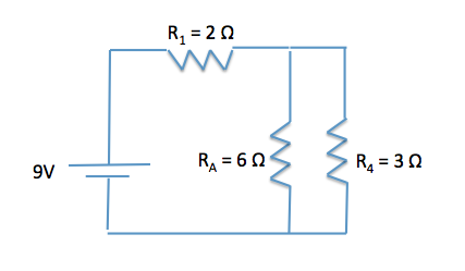
During the cold winter months, some gloves have the ability to provide extra warmth due to an internal heating source. A simplified circuit, similar to those in electric gloves, is comprised of a 9 V battery with no internal resistance and three resistors as shown in the image below.
What direction do electrons flow through the circuit?
Counterclockwise
Cannot be determined
Clockwise
Counterclockwise
Remember that convention dictates that current flows in the direction of positive charge (protons), thus, electrons flow in the opposite direction. Also remember that the larger length on the battery symbol on the circuit diagram indicates that current flows in this direction. In the diagram below, we can see that current flows clockwise, thus electrons flow counterclockwise.

Example Question #62 : Electricity And Magnetism
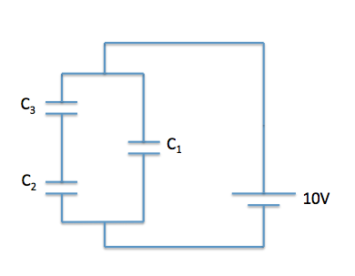
Batteries and AC current are often used to charge a capacitor. A common example of capacitor use is in computer hard drives, where capacitors are charged in a specific pattern to code information. A simplified circuit with capacitors can be seen below. The capacitance of C1 is 0.5 μF and the capacitances of C2 and C3 are 1 μF each. A 10 V battery with an internal resistance of 1 Ω supplies the circuit.

What direction is current flowing through the circuit?
Cannot be determined
Clockwise
Counterclockwise
Counterclockwise
Remember that convention dictates that current flows in the direction of positive charge (protons). Also remember that the larger length on the battery symbol on the circuit diagram indicates that current flows in this direction. In the diagram below, we can see that current flows counterclockwise.

Example Question #41 : Ap Physics 2
During the cold winter months, some gloves have the ability to provide extra warmth due to an internal heating source. A simplified circuit, similar to those in electric gloves, is comprised of a 9V battery with no internal resistance and three resistors as shown in the image below.
How much current flows through resistor R4?


First, we need to determine the voltage drop across R4. Given that RA and R4 are in parallel, we know that the voltage drop across each is the same.
The voltage drop across R1 can be calculated using the Icircuit (all the current generated by the battery’s potential difference must pass through R1 because it is in direct series with the battery), and the resistance of the resistor.
I can be calculated by V = IR because we have the voltage drop across the circuit (9 V) and can calculate the equivalent resistance:


By taking the inverse of the equation, we can see that RA4 is equal to 2Ω.
Req = RA4 + R1 = 2Ω + 2Ω = 4Ω
Now, using V=IR allows us to find the current in the circuit.
V = IR
I = V/R = 9V/4Ω = 2.25 A
Plugging this value in, we can find the voltage drop across R1.
VR1 = IR = (2.25 A)(2Ω) = 4.5 V
Now we can determine the voltage drop across the parallel resistors by subtracting the voltage drop across R1 from the battery.
VA = 9V – 4.5V = 4.5V
this value will be the same for either RA or R4. We can now use V = IR to determine the amount of current that flows through R4.
V = IR
I = V/R = 4.5V/3Ω = 1.5A
Additionally, due to Kirchhoff’s first law, we know that current in must equal current out in a junction. Thus, because R4 has 1.5 A of current, RA must have 0.75A. Thus makes logical sense because electrons take the path of least resistance, meaning the resistor with the lowest resistance will have the greater current.
Example Question #33 : Circuits
During the cold winter months, some gloves have the ability to provide extra warmth due to an internal heating source. A simplified circuit, similar to those in electric gloves, is comprised of a 9V battery with no internal resistance and three resistors as shown in the image below.
What is the current that flows through the circuit?


Because we are being asked the current that flows through the circuit, we can use the formula V = IR because we have the voltage drop across the circuit (9V) and can calculate the equivalent resistance.


By taking the inverse of the equation, we can see that RA4 is equal to 2Ω.
Req = RA4 + R1 = 2Ω + 2Ω = 4Ω
Now, using V = IR, we can find the current.
V = IR
I = V/R = 9V/4Ω = 2.25A
Example Question #73 : Ap Physics 2
If the peak voltage across a 


First, find the rms voltage across the resistor with the equation:

The pure voltage is 

Now we can use Ohm's law to find the rms current.


Example Question #1 : Current
A 12V battery is connected in a circuit containing two resistors in parallel. The resistors have resistances of 


Regardless of whether the 

For resistors in parallel, each component/branch will have the same voltage drop, but the current may vary. Initially, the voltage through the
\rightarrow I_o=6A")
After the
\rightarrow I_f=6A")
Example Question #33 : Circuits
Consider the following circuit:


Water has been spilt on the circuit, occasionally creating a short in the circuit. The short is represented by the switch, which is closed when the circuit is shorted. What is the difference in power loss through the circuit when the switch is closed compared to being open?


We will need to calculate total equivalent resistance for each of the two scenarios to calculate power losses.
SCENARIO 1: Switch Closed
When the switch is closed, a resistance-free path is created. This effectively reduces the current flow through the parallel resistors to zero. Therefore, we have a much simpler circuit, consisting only of R1 and R5. Since they are in series, we can simply add them:

The expression for power is:

Substituting Ohm's law for current, we get:
V=\frac{V^2}{R}")
Plugging in our values, we get:
^2}{7\Omega} = 20.57 W")
SCENARIO 2: Switch Open
Now that we have resistors in parallel, it will take two steps to condense the circuit. For the parallel part, we get:


Now, since everything is in series in this equivalent circuit, we can simply add it all up:

Again using the formula for power, we get:
^2}{\frac{71}{8}\Omega} = 16.23 W")
Now we can calculate the difference between the two scenarios:

Example Question #31 : Circuits
A 


Relevant equations:

When the circuit is first connected, the current increases from zero to its final value. During this time as the current changes, the inductor has a voltage across it. After a long period, the current has built up to its maximum value.
After a long period, 

Plugging in our values for voltage and resistance, we can solve for the final current.

Example Question #2 : Current
An circuit contains a 


Relevant equations:

The current is maximized when the power supply frequency, 

(250*10^{-9}C)}}=\frac{1}{\sqrt{1*10^{-8}}}=\frac{1}{1*10^{-4}}= 10,000 \frac{rad}{s}")
Example Question #32 : Circuits
An circuit consists of a 


Relevant equations:

}")


Step 1: Find impedance, 

Step 2: Calculate 


Step 3: Use 


Certified Tutor

Certified Tutor

All MCAT Physical Resources