AP Physics 2 : AP Physics 2
Study concepts, example questions & explanations for AP Physics 2


All AP Physics 2 Resources
Example Questions
Example Question #2 : Circuits
What is the resistance in a wire carrying a voltage of 


The formula we can use here is the power formula that involved both resistance and voltage:

We are given the voltage and power, allowing us to solve for the resistance.
^2}{R}")


Example Question #61 : Ap Physics 2
A 


To find resistance from voltage and current, we will need to use Ohm's law:


We are given the voltage and current, allowing us to solve for the resistance.

Example Question #211 : Electricity And Waves
An electrician wishes to cut a copper wire ")


9.6m
2.6cm
10cm
38m
960m
960m
To relate resistance R, resistivity 

Rearranging to isolate the quantity we wish to solve for, L, gives the equation 
^{2}=1.65 * 10^{-6}m^{2}")
Plugging in our numbers gives the answer, 960m.

Example Question #1 : Resistors And Resistance
During the cold winter months, some gloves have the ability to provide extra warmth due to an internal heating source. A simplified circuit, similar to those in electric gloves, is comprised of a 9V battery with no internal resistance and three resistors as shown in the image below.
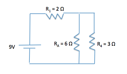
What is the net resistance of the circuit?


First we need to combine the resistors in parallel.


By taking the inverse of the equation, we can see that RA4 is equal to 2Ω.
Now that we have simplified the two resistors in parallel, we need to determine how the Req of the two parallel resistors and the resistance due to R1 are arranged. We can see that these resistors are now in series, thus we can directly add their resistances together to get the overall resistance of the circuit.
Req = RA4 + R1 = 2Ω + 2Ω = 4Ω
Remember as a general rule, the equivalent resistance of resistors in series is an arithmetic sum of their individual resistances.
Example Question #2 : Circuits
During the cold winter months, some gloves have the ability to provide extra warmth due to an internal heating source. A simplified circuit, similar to those in electric gloves, is comprised of a 9V battery with no internal resistance and three resistors as shown in the image below.
Instead of assuming that the 9V battery has no internal resistance, what would the terminal potential of the battery be if it has an internal resistance of 


Remember that internal resistance lowers the EMF of the battery. We need to calculate the voltage drop that would occur inside the battery, and then subtract that from the “stated” voltage to determine the terminal potential of the battery.
We first need the current supplied by the battery. We can use the formula V = IR because we have the voltage drop across the circuit (9V) and can calculate the equivalent resistance.


By taking the inverse of the equation, we can see that RA4 is equal to 2Ω.
Req = RA4 + R1 = 2Ω + 2Ω = 4Ω
Now, using V=IR, we can find the current in the circuit.
V = IR
I = V/R = 9V/4Ω = 2.25A
Plugging in this value with the internal resistance of the battery gives us the voltage decrease.
V = IR = (2.25A)(0.9Ω) = 2.025V
Terminal Potential = 9V – 2.025V = 6.975V
As we can see, battery companies are interested in keeping the internal resistance of batteries at a minimum, because it lowers the overall terminal potential of the battery.
Example Question #1 : Capacitors And Dielectrics
Capacitors with capacitances of 3 μF, 7 μF and 10 μF are wired in parallel. What is the capacitance of the circuit?
- it cannot be determined without knowing the resistance of the circuit
- it cannot be determined without knowing the time constant in the circuit
- 20 μF
- approximately 1.75 μF
- none of these is correct
2
5
1
4
3
3
Response 3 is the correct choice. Electrons will space themselves as far apart as possible, because of charge repulsion; therefore, in a parallel arrangement, they will jump onto each capacitor and “load it up.” The parallel capacitance is calculated by simply adding the individual values. The value would be about 1.75 μF if the three were connected in series, where the formula is 
Example Question #62 : Ap Physics 2
A 


First find the equivalent capacitance of the two capacitors by adding their inverses.


Then, we can find the charge stored on this equivalent capacitor.

For capacitors in series the charges on each must be equal, and also equal to the charge on the equivalent capacitor. The answer is 
Example Question #2 : Capacitors And Dielectrics
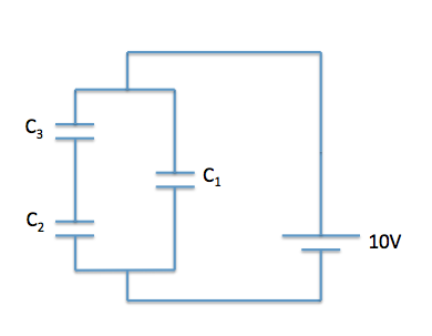
Batteries and AC current are often used to charge a capacitor. A common example of capacitor use is in computer hard drives, where capacitors are charged in a specific pattern to code information. A simplified circuit with capacitors can be seen below. The capacitance of C1 is 0.5 μF and the capacitances of C2 and C3 are 1 μF each. A 10 V battery with an internal resistance of 1 Ω supplies the circuit.

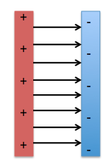
How is the charge stored on the capacitor?
Evenly distributed inside the capacitor
Evenly distributed on the capacitor surface
Unevenly distributed on the capacitor surface
Unevenly distributed inside the capacitor
Evenly distributed on the capacitor surface
Charge is evenly distributed on the surface of the capacitor. If we think back to electric force, we know that positive charges repel other positive charges and negative charges repel other negative charges; thus, the charges are evenly distributed to minimize the force between them. We can see how this looks in diagrammatic form below.
Example Question #71 : Electricity And Magnetism
Batteries and AC current are often used to charge a capacitor. A common example of capacitor use is in computer hard drives, where capacitors are charged in a specific pattern to code information. A simplified circuit with capacitors can be seen below. The capacitance of C1 is 0.5 μF and the capacitances of C2 and C3 are 1 μF each. A 10 V battery with an internal resistance of 1 Ω supplies the circuit.
What is the equivalent capacitance of C2 and C3?
3μF
0.33μF
2μF
0.5μF
0.5μF
First, we need to determine how these capacitors are being added. We can see that they are being added in in series. Remember that capacitors in series are added as reciprocals:

Ceq = 0.5μF
Example Question #3 : Capacitors And Dielectrics
Batteries and AC current are often used to charge a capacitor. A common example of capacitor use is in computer hard drives, where capacitors are charged in a specific pattern to code information. A simplified circuit with capacitors can be seen below. The capacitance of C1 is 0.5 μF and the capacitances of C2 and C3 are 1 μF each. A 10 V battery with an internal resistance of 1 Ω supplies the circuit.
What is the equivalent capacitance of the circuit?
1μF
3μF
4μF
2μF
1μF
First, we need to determine how capacitors C2 and C3 are being added. We can see that they are being added in in series. Remember that capacitors in series are added as reciprocals.

C23 = 0.5μF
Next, we need to determine how we can find the Ceq by simplifying C23 and C1. We can see that Ceq and C1 are in parallel, thus we can directly add the individual capacitances.
Ceq = C23 + C1 = 0.5μF + 0.5μF = 1μF

Certified Tutor

Certified Tutor

All AP Physics 2 Resources