MCAT Physical : Resistors and Resistance
Study concepts, example questions & explanations for MCAT Physical


All MCAT Physical Resources
Example Questions
Example Question #1 : Resistors And Resistance
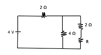
What is the resistance through resistor R given that the current through the circuit is 1 A?
4 Ω
1 Ω
2 Ω
0.5 Ω
2 Ω
In order to solve this problem, we must understand that the resistance of parallel resistors is added inversely and that series resistors are added directly.
Series

Parallel
Ohm’s Law

We can first find the total resistance of the circuit to be 4 Ω using ohm's law . Then by subtracting the resistor in series (2 Ω) from the total resistance, we can set the remaining parallel resistors equal to 2 Ω. Finally, we can use the parallel resistor equation to find R. Remember that you can simply count the two resistors in series on the far right branch of the circuit (R and 2 Ω) as one number in the parallel resistor formula giving us
we can solve for this to find that R = 2 Ω
Example Question #1 : Resistors And Resistance
Which of these statements is false?
- In the case of parallel resistors, the greatest current flow will occur across the highest resistor.
- In the case of parallel resistors, the greatest current flow will occur across the lowest resistor.
- In the case of series resistors, the current flow is the same through each resistor.
- In the case of series resistors, the voltage drop is greatest across the highest resistor.
- All are false.
5
2
4
3
1
1
Choice 1 is a false statement, and therefore the correct response. Electrical potential energy (voltage), like water, always flows downhill along the path of least resistance. In the situation of parallel resistors, the greatest current flow will be through the lowest resistor.
(Mnemonic: Think of an ultra-low resistor = a wire. The current would preferentially flow through the wire rather than, for example, a one million Ohm resistor.) In an electrical circuit, the current entering the circuit from one pole of the battery and the current re-entering the other pole of the battery must be the same, although the voltage is exhausted by passing through the various resistors in the circuit in direct proportion to the degree of resistance each causes.
Example Question #2 : Resistors And Resistance
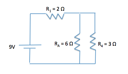
During the cold winter months, some gloves have the ability to provide extra warmth due to an internal heating source. A simplified circuit, similar to those in electric gloves, is comprised of a 9 V battery with no internal resistance and three resistors as shown in the image below.
What happens to the energy that is dissipated by the resistors?
Stored as potential energy
Not enough information provided to determine
Dissipated as light
Dissipated as heat
Dissipated as heat
Resistors serve to drop voltage over a certain distance by providing friction for electrons to move against. As with other types of friction, including kinetic and static contact friction and air resistance, energy is lost as heat to the surrounding environment. The same is true in the circuits of these winter gloves. The resistors allow the energy provided by the battery to be dissipated as heat, warming the person's hands during the cold winter months.
Example Question #53 : Ap Physics 2
During the cold winter months, some gloves have the ability to provide extra warmth due to an internal heating source. A simplified circuit, similar to those in electric gloves, is comprised of a 9 V battery with no internal resistance and three resistors as shown in the image below.
What is the total resistance of the two resistors in parallel (RA and R4)?
1/2Ω
2Ω
9/2Ω
9Ω
2Ω
First, we need to determine how the resistors are being added. As we can see in the circuit diagram, the two resistors are being added in parallel. In parallel, we should expect an equivalent resistance lower that that of each individual resistor.


By taking the inverse of the equation, we can see that Req is equal to 2Ω.
Remember as a general rule, the equivalent resistance of resistors in parallel is lower than that of either resistor in the parallel circuit.
Example Question #53 : Ap Physics 2
During the cold winter months, some gloves have the ability to provide extra warmth due to an internal heating source. A simplified circuit, similar to those in electric gloves, is comprised of a 9 V battery with no internal resistance and three resistors as shown in the image below.
What would happen to the equivalent resistance if R1 were in parallel with RA and R4, instead of in series?
Remain the same
Decrease
Increase
Decrease
The equivalent resistance would decrease. Remember that adding resistors in parallel decreases the equivalent resistance of the circuit. If we calculated the new resistance assuming R1 was in parallel with the other resistors, we would find the following.
1/Req = 1/R1 + 1/RA + 1/R4 = 1/2Ω + 1/6Ω + 1/3Ω = 3/6Ω + 1/6Ω + 2/6Ω = 6/6Ω
By taking the inverse of the equation, we can see the equivalent resistance decreases to Req = 1 Ω, which is less than the resistance of any individual resistor.
Example Question #5 : Resistors And Resistance
Use the following information to answer questions 1-6:
The circulatory system of humans is a closed system consisting of a pump that moves blood throughout the body through arteries, capillaries, and veins. The capillaries are small and thin, allowing blood to easily perfuse the organ systems. Being a closed system, we can model the human circulatory system like an electrical circuit, making modifications for the use of a fluid rather than electrons. The heart acts as the primary force for movement of the fluid, the fluid moves through arteries and veins, and resistance to blood flow occurs depending on perfusion rates.
To model the behavior of fluids in the circulatory system, we can modify Ohm’s law of V = IR to ∆P = FR where ∆P is the change in pressure (mmHg), F is the rate of flow (ml/min), and R is resistance to flow (mm Hg/ml/min). Resistance to fluid flow in a tube is described by Poiseuille’s law: R = 8hl/πr4 where l is the length of the tube, h is the viscosity of the fluid, and r is the radius of the tube. Viscosity of blood is higher than water due to the presence of blood cells such as erythrocytes, leukocytes, and thrombocytes.
The above equations hold true for smooth, laminar flow. Deviations occur, however, when turbulent flow is present. Turbulent flow can be described as nonlinear or tumultuous, with whirling, glugging or otherwise unpredictable flow rates. Turbulence can occur when the anatomy of the tube deviates, for example during sharp bends or compressions. We can also get turbulent flow when the velocity exceeds critical velocity vc, defined below.
vc = NRh/ρD
NR is Reynold’s constant, h is the viscosity of the fluid, ρ is the density of the fluid, and D is the diameter of the tube. The density of blood is measured to be 1060 kg/m3.
Another key feature of the circulatory system is that it is set up such that the organ systems act in parallel rather than in series. This allows the body to modify how much blood is flowing to each organ system, which would not be possible under a serial construction. This setup is represented in Figure 1.
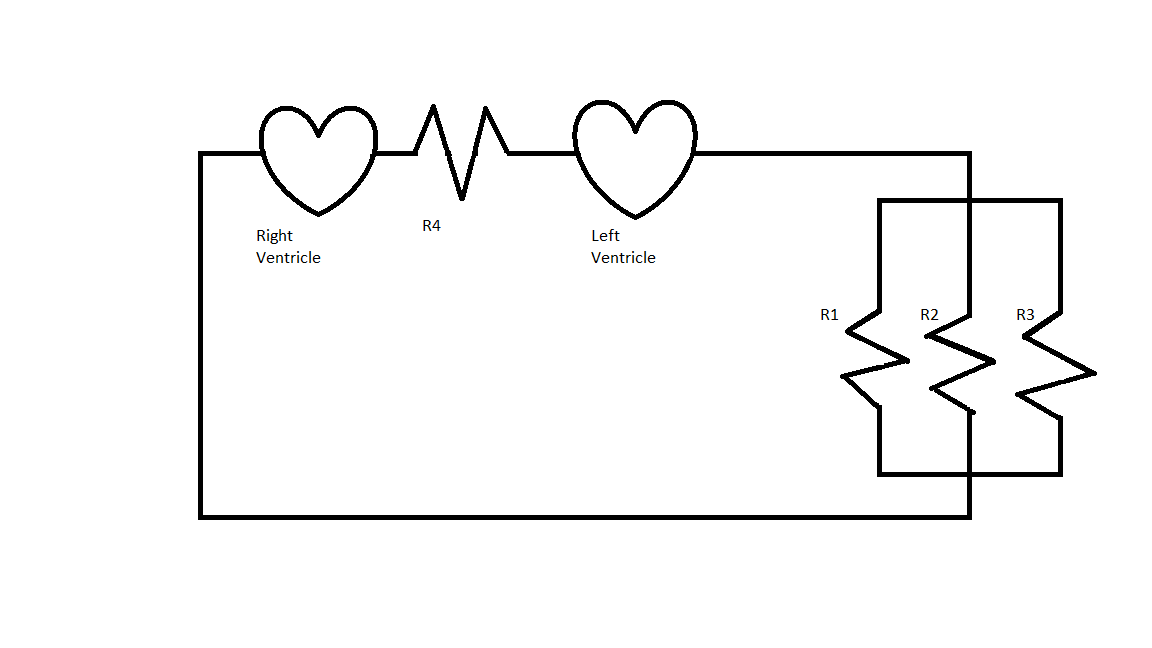
Assume that in Figure 1 R1 = 1/2 mmHg/ml/min, R2 = 2 mmHg/ml/min, R3 = 4 mmHg/ml/min, and R4 = 4 mmHg/ml/min.
The pressure generated by the left ventricle is 100mmHg and the pressure generated from the right ventricle is 50mmHg. What is the rate of flow across R3?
50ml/min
100ml/min
25ml/min
75ml/min
25ml/min
For a parallel circuit, voltage remains constant. Analogously, pressure remains constant in this scenario. If we know the pressure and the resistance, we can find the current flow through the resistor by using ∆P = FR.
In this case, we will use only the left ventricle pressure, since that is the pressure pumped to the rest of the body, whereas the right ventricle only pumps to the lungs. Using ∆P = FR we can rearrange this to give us F = ∆P/R. Plugging in the numbers we can solve for F.

Example Question #3 : Resistors And Resistance
Use the following information to answer questions 1-6:
The circulatory system of humans is a closed system consisting of a pump that moves blood throughout the body through arteries, capillaries, and veins. The capillaries are small and thin, allowing blood to easily perfuse the organ systems. Being a closed system, we can model the human circulatory system like an electrical circuit, making modifications for the use of a fluid rather than electrons. The heart acts as the primary force for movement of the fluid, the fluid moves through arteries and veins, and resistance to blood flow occurs depending on perfusion rates.
To model the behavior of fluids in the circulatory system, we can modify Ohm’s law of V = IR to ∆P = FR where ∆P is the change in pressure (mmHg), F is the rate of flow (ml/min), and R is resistance to flow (mm Hg/ml/min). Resistance to fluid flow in a tube is described by Poiseuille’s law: R = 8hl/πr4 where l is the length of the tube, h is the viscosity of the fluid, and r is the radius of the tube. Viscosity of blood is higher than water due to the presence of blood cells such as erythrocytes, leukocytes, and thrombocytes.
The above equations hold true for smooth, laminar flow. Deviations occur, however, when turbulent flow is present. Turbulent flow can be described as nonlinear or tumultuous, with whirling, glugging or otherwise unpredictable flow rates. Turbulence can occur when the anatomy of the tube deviates, for example during sharp bends or compressions. We can also get turbulent flow when the velocity exceeds critical velocity vc, defined below.
vc = NRh/ρD
NR is Reynold’s constant, h is the viscosity of the fluid, ρ is the density of the fluid, and D is the diameter of the tube. The density of blood is measured to be 1060 kg/m3.
Another key feature of the circulatory system is that it is set up such that the organ systems act in parallel rather than in series. This allows the body to modify how much blood is flowing to each organ system, which would not be possible under a serial construction. This setup is represented in Figure 1.
Due to the parallel circuit, the circulatory system has the ability to modify the flow of blood to different organs in the body. The body does this by dilating or constricting vessels to change resistance, and thus the flow of blood.
Assume that, in the diagram in Figure 1, all of the resistances are initially equal. In order to direct more blood flow through R3, the body reduces the resistance to R3 by dilating vessels, and increases R1 and R2 equally by restricting vessels. Assume Rb is the resistance to blood flow through the body from the left ventricle, and it remains constant. What is the value of R3 in terms of Rb?
R3 = 2Rb
R3 = 4Rb
R3 = 8Rb
R3 = Rb
R3 = 2Rb
We need to use the parallel resistance equation.

R4 is not included since that is part of a different circulatory circuit; we are only concerned with blood flow to the body, not the lungs. We are told that they all start with the same resistance, so R1 = R2 = R3, which we can just call R.
Now, given V = IR, in order for flow to double across a parallel resistor, since voltage is constant, resistance must decrease by a factor or two. Now R3 = (1/2)R.
We can rewrite the initial equation and solve for R.


We can now solve for R3 using the relationship between R3 and R discussed earlier.

Example Question #4 : Resistors And Resistance

If each resistor in the diagram above has resistance 


Resistors add differently, depending on their orientation in series or in parallel. The three resistors furthest to the right are in series and can be simplified to 
Now this "


This method can be repeated for the next sets of resistors in series and in parallel.
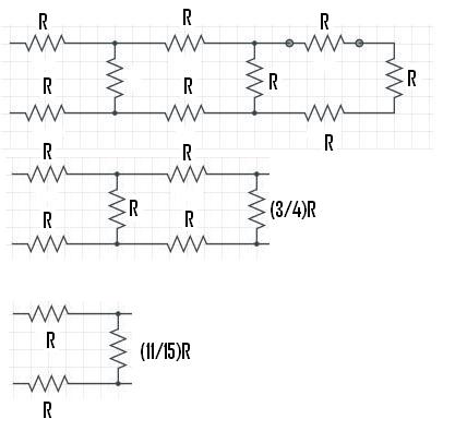
For the final calculation, 
Example Question #51 : Ap Physics 2
Given the three resistors below, find the approximate ratio of the equivalent reistance for these resistors in series to their equivalent resistance in parallel.


For resistors in series, 

For resistors in parallel, 


The ratio of series to parallel will be 
Example Question #2 : Resistors And Resistance
During the cold winter months, some gloves have the ability to provide extra warmth due to an internal heating source. A simplified circuit, similar to those in electric gloves, is comprised of a 9V battery with no internal resistance and three resistors as shown in the image below.
What is the net resistance of the circuit?


First we need to combine the resistors in parallel.


By taking the inverse of the equation, we can see that RA4 is equal to 2Ω.
Now that we have simplified the two resistors in parallel, we need to determine how the Req of the two parallel resistors and the resistance due to R1 are arranged. We can see that these resistors are now in series, thus we can directly add their resistances together to get the overall resistance of the circuit.
Req = RA4 + R1 = 2Ω + 2Ω = 4Ω
Remember as a general rule, the equivalent resistance of resistors in series is an arithmetic sum of their individual resistances.

Certified Tutor

Certified Tutor

All MCAT Physical Resources