ACT Science : How to find synthesis of data in physics
Study concepts, example questions & explanations for ACT Science


All ACT Science Resources
Example Questions
Example Question #91 : Physics
Mary is performing an experiment involving the electromagnetic spectrum. She observes several different types of waves and records their wavelength, frequency, and speed.
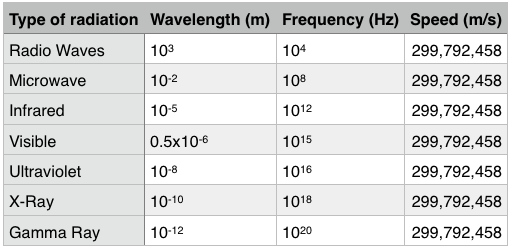
FM radio waves are at the higher end of the radio wave frequency spectrum. Which of the following could be possible value for the frequency of an FM radio wave?


If FM radio waves are at the higher end of radio wave frequency, then they are closer to microwaves. The only possible answer choice between the frequency of radio waves and the frequency of microwaves is 

Example Question #92 : Physics
Mary is performing an experiment involving the electromagnetic spectrum. She observes several different types of waves and records their wavelength, frequency, and speed.
Which of the following would be a valid conclusion for this experiment?
Frequency and speed are inversely proportional
Frequency and wavelength are directly proportional
Frequency and speed are directly proportional
Frequency and speed are unrelated
Frequency and speed are unrelated
All of the waves move with the same speed; therefore, there is no relationship.
Another valid conclusion would be that wavelength and frequency are inversely proportional. As frequency increases, wavelength decreases.
Example Question #93 : Physics
A fiber optic Michelson interferometer is a device that detects changes in optical paths. In a fiber optic interferometer, a coherent light source (usually a laser) is sent through a beam splitter that splits the light along two paths. These beams are coupled into fiber optic cables that can be arranged and manipulated more freely than mirrors. The two beams are finally recombined by a second beam splitter and superimposed on a screen. If there is a phase difference between the two waves, interference fringes will be viewed on the screen.
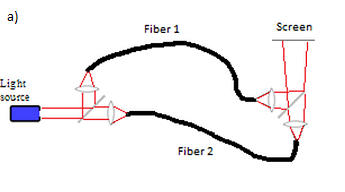
By observing fringe shifts, one can quantify the change in optical path difference between the two fibers using the following equation:

where m is the number of fringe shifts, x is the difference between the optical paths of the two beams, and 
Experiment 1:
A student sets up a fiber optic Michelson interferometer and heats one of the fibers with various resistors and power supplies, fans air over one of the fibers, and then bends one of the fibers. The resulting fringe shifts, as well as the change in optical path difference (OPD), are shown below.
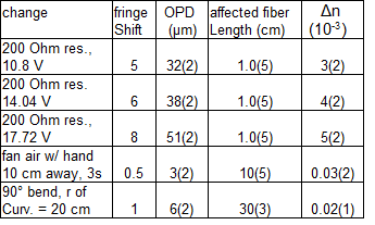
The experiment is set up correctly and measurements are taken. If 0 fringe shifts are measured, what can we conclude from the experiment?
The optical path difference between the two beams is zero.
The rate of change of the optical path difference is constant.
The optical path difference between the two beams does not change.
The optical path difference is negligible.
The optical path difference between the two beams does not change.
Recall from the question statement that fringe shifts relate to the change in the optical path difference, not the optical path difference itself. Therefore, we can only conclude that the optical path difference has not changed.
Example Question #94 : Physics
A fiber optic Michelson interferometer is a device that detects changes in optical paths. In a fiber optic interferometer, a coherent light source (usually a laser) is sent through a beam splitter that splits the light along two paths. These beams are coupled into fiber optic cables that can be arranged and manipulated more freely than mirrors. The two beams are finally recombined by a second beam splitter and superimposed on a screen. If there is a phase difference between the two waves, interference fringes will be viewed on the screen.
By observing fringe shifts, one can quantify the change in optical path difference between the two fibers using the following equation:

where m is the number of fringe shifts, x is the difference between the optical paths of the two beams, and 
Experiment 1:
A student sets up a fiber optic Michelson interferometer and heats one of the fibers with various resistors and power supplies, fans air over one of the fibers, and then bends one of the fibers. The resulting fringe shifts, as well as the change in optical path difference (OPD), are shown below.
If a measured fringe shift is written as 
10%
20%
1%
5%
20%
The way to calculate percent uncertainty is to divide the uncertainty by the measured value. We have

or 20%.
Example Question #1214 : Act Science
A student was interested in determining the relationship between the current, voltage, and resistance in a direct circuit, such as those exemplified by batteries connected to light bulbs. The student built the circuit presented in Figure 1 using a 2 ohm resistor.
Figure 1:
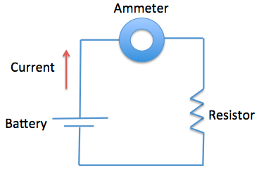
The current that flows through the circuit can be calculated using the equation 


The student used a 2 ohm resistor and batteries of various voltages to obtain the results in Table 1. The currents shown in the table are NOT calculated using the formula 
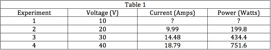
If the student didn't know the resistance in the resistor, what formula could he use to approximate it?


None of the other answer choices
Given the formula in the passage, we know that 
Example Question #1215 : Act Science
A student was interested in determining the relationship between the current, voltage, and resistance in a direct circuit, such as those exemplified by batteries connected to light bulbs. The student built the circuit presented in Figure 1 using a 2 ohm resistor.
Figure 1:
The current that flows through the circuit can be calculated using the equation
The student used a 2 ohm resistor and batteries of various voltages to obtain the results in Table 1. The currents shown in the table are NOT calculated using the formula
Based on Table 1, if a battery of 50 V were used in the circuit, what would be the most likely amount of current to flow through the circuit?
23.23 A
20.20 A
5.49 A
30.35 A
23.23 A
The most likely current can be calculated by rearranging the formula provided in the passage or by looking at the trend in Table 1. If we use the formula, we see that 
Example Question #1216 : Act Science
A student was interested in determining the relationship between the current, voltage, and resistance in a direct circuit, such as those exemplified by batteries connected to light bulbs. The student built the circuit presented in Figure 1 using a 2 ohm resistor.
Figure 1:
The current that flows through the circuit can be calculated using the equation
The student used a 2 ohm resistor and batteries of various voltages to obtain the results in Table 1. The currents shown in the table are NOT calculated using the formula
The passage and Table 1 present results with ideal batteries that do not have any internal resistance. If the batteries used were a real batteries that had internal resistance, how would the measured currents of the system change?
It would increase.
It would decrease.
It cannot be determined how current would change.
It would remain the same.
It would decrease.
If the batteries used in the circuit were to have additional resistance, then the overall resistance of the circuit would increase. Because we know that current and resistance are inversely related by 

Example Question #1217 : Act Science
A student was interested in determining the relationship between the current, voltage, and resistance in a direct circuit, such as those exemplified by batteries connected to light bulbs. The student built the circuit presented in Figure 1 using a 2 ohm resistor.
Figure 1:
The current that flows through the circuit can be calculated using the equation
The student used a 2 ohm resistor and batteries of various voltages to obtain the results in Table 1. The currents shown in the table are NOT calculated using the formula
In Experiment 3, if the student were to use the same 30 V battery with a 4 ohm resistor instead of a 2 ohm resistor, how would the current of the system change?
It would remain the same.
It would increase
It would decrease.
It cannot be determined how current would change.
It would decrease.
Given Table 1 and the equation 

Example Question #1216 : Act Science
A student was interested in determining the relationship between the current, voltage, and resistance in a direct circuit, such as those exemplified by batteries connected to light bulbs. The student built the circuit presented in Figure 1 using a 2 ohm resistor.
Figure 1:
The current that flows through the circuit can be calculated using the equation
The student used a 2 ohm resistor and batteries of various voltages to obtain the results in Table 1. The currents shown in the table are NOT calculated using the formula
In Experiment 2, if the student were to use the same 20 V battery with a 3 ohm resistor instead of a 2 ohm resistor, how would the power of the circuit change?
It would decrease.
It would increase.
It would remain the same.
It cannot be determined how power would change.
It would decrease.
Given Table 1 and the equation 

Example Question #1218 : Act Science
A student was interested in determining the relationship between the current, voltage, and resistance in a direct circuit, such as those exemplified by batteries connected to light bulbs. The student built the circuit presented in Figure 1 using a 2 ohm resistor.
Figure 1:
The current that flows through the circuit can be calculated using the equation
The student used a 2 ohm resistor and batteries of various voltages to obtain the results in Table 1. The currents shown in the table are NOT calculated using the formula
Based on the results in Table 1, the power of Experiment 1 would most likely be __________.
202.1 watts
49.8 watts
0 watts
142.1 watts
49.8 watts
Knowing that the resistance of the resistor is 2 ohms and that current can be calculated using 


All ACT Science Resources